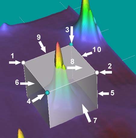
Fig.1 3D Window screen shot with surface, orthogonal planes, pin read out markers and axis shown.
All tools are movable in intuitive manner with mouse drag within 3d window operation.
The program has intuitive user interface designed for easy use. Here you can find description of the interface mouse functions. Some of the tools has tool tips as well.
Interactive Objects (measurement tools) within 3D Window
Fig.1 3D
Window screen shot
with surface, orthogonal planes, pin read out markers and axis shown.
All tools
are movable in intuitive manner with mouse drag within 3d window operation.
| Background,
(1) in Fig.1 anywhere out of 3D objects |
Left Mouse Drag rotate the surface |
| Surface,
(2) in Fig.1 any surface point within 3D window |
Left
Mouse Drag rotate the surface Mouse Move read X,Y,Z position (while XYZ is enabled, see "Tools" menu |
| Cut Plane Y (Y-Slicer), (3) in Fig.1 | Left
Mouse Down select Y-Slicer Left Mouse Drag move the slicer |
| Horizontal
Cut Plane (Z-Slicer), (4) in Fig.1 within semi-transparent cutting plane |
Left
Mouse Down select Z-Slicer Left Mouse Drag move the slicer |
| Distance
Tool, Pin markers, (5) in Fig.1 |
Left
Mouse Down select one of the Pins Left Mouse Drag move selected Pin |
| Tools | |
3D Volume Tool
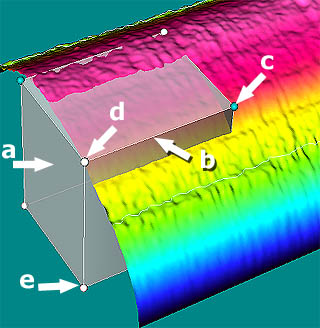
Fig.2 3D Volume Tool:: Clickable anchors (points) planes and borders .:See more detail:. |
|
| a - Walls | Left Mouse Drag
resize X,Y the volume tool Right Mouse Drag move X,Y the volume tool as the whole |
| b - Border at the top plane (white) | Left Mouse Drag
resize Z the volume tool upper plane is moved up/down |
| c - Anchor point at the top plane (cyan) | Left Mouse Drag resize X,Y the volume tool |
| d - Anchor point at the top plane (white) | Left Mouse Drag
resize Z the volume tool upper plane is moved up/down |
| e - Anchor point
at the buttom plane (white) .:See more detail:. |
Left Mouse Drag
resize Z the volume tool Down (lower) plane is moved up/down |
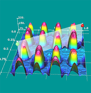
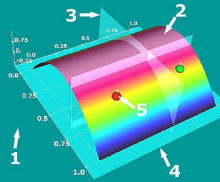
Fig. 3. Cut tool:: Clickable anchors (points) The cut is read and drawn into 2D cut form |
|
| Anchoprs (green, red) | Left Mouse Drag resize X,Y the volume tool |
Light
position Tool 
Designed to give user easy access to the lighting subsystem. Controls position of the main light relative to the surface. Visual effect of the light is just the same as in real life. It changes reflection and shadows. Useful to visualize hidden surface features by shadowing. |
Left
Mouse Drag within the tool (not necessarily within the red marker)
This operation changes the light position. Red marker shows relative position of the light. Right Mouse Click Submenu to restore Default light position |
Palette
and Contour Tool 
Palette is shown within this tool as colors of Look Up Table (LUT) is shown as white shadowed lines of Z elevation. Numbers give corresponding Z-value (height) |
Left Mouse Click - increase number of contour lines Right Mouse Click - decrease number of contour lines |
Clickable
features: Left Mouse
1. White anchor, sphere: Operation Drag (mouse down and move) used to change
XY position of anchor, which results in XY resizing of the box.
2. White anchor, sphere: Operation Drag (mouse down and move) used to change
XY position of anchor, which results in XY resizing of the box.
3. Cyan anchor, sphere: Operation Drag (mouse down and move) used to change
Z position of the upper plane. Results in resizing of the box height.
4. Cyan anchor, sphere: Operation Drag (mouse down and move) used to change
Z position of the upper plane. Results in resizing of the box height.
5. Side corners of the box, Vertical white lines: Operation Drag (mouse down
and move) used to change XY position of anchor, which results in XY resizing
of the box.
6. Side plane of the box: Operation Drag (mouse down and move) used to change
XY position of anchor, which results in XY resizing of the box.
7. Side plane of the box: Operation Drag (mouse down and move) used to change
XY position of anchor, which results in XY resizing of the box.
8. Side plane of the box: Operation Drag (mouse down and move) used to change
XY position of anchor, which results in XY resizing of the box.
Note even though upper plane is semitransparent. The drag mouse through upper
plane will activate side plane rather than upper plane.
9. Corners at the Upper Plane, white lines: Operation Drag (mouse down and move)
used to change Z position of the upper plane. Results in resizing of the box
height.
10. Corners at the Upper Plane, white lines: Operation Drag (mouse down and
move) used to change Z position of the upper plane. Results in resizing of the
box height.
Clickable
features: Right Mouse
Any clickable 3D object above if used with Right mouse produces Volume Tool
Move effect: Operation Right Mouse Drag.
Advanced
3D Visualization for AFM, SPM, SEM and TEM microscopy: Home
ATI™
is used under license and is a registered trademark of ATI Technologies Inc.
in the United States and other countries.
OpenGL
is a registered trademark of SGI
-----------------------------------------------
Copyright
© 2003-2013 ScienceGL,
Inc.