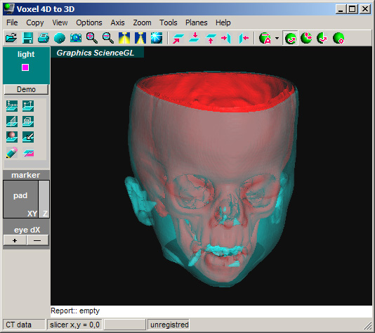
Fig.1. Screen Shot 4D image stack (CT data ) to 3D isosurface constructor is ON, default settings. CT data is loaded, isosurfaces are constructed at default threshold levels.
Red Surface is solid, while cyan is semitransparent.
Volume_4D Advanced Medical CT/MRI Visualization Software: 4D to stereo 3D package
Quick
Demo Help
GENERAL
ScienceGL offers 4D stack data visualization / analysis software solutions for medical Computed Tomographpy (CT), Magnetic Resonance Imaging (MRI), Ultrasound Imaging. Our software is packed with unique interactive measurement tools that lets you to discover more things in less time. This version also supports stereo 3D display.
1. Install
Run **.MSI Microsoft Standard Installation file. Find the icon with shortcut to program on your desktop. Run the program.
2. Start
Run the program. The Computed Tomographpy (also known as computerized tomography, CT). The multiple CT stack image is loaded automatically. See the 3D isosurface default screen with 2 iso-surfaces auto constructed. Observe default mouse interaction mode. Drag the mouse within 3D screen to perform rotation. Adjust stereo perception with "eye dX" eye separation buttons on the left side of the main form. Zoom 3D with mouse and Alt key pressed. Pan 3D with mouse and Shift key pressed. Press "Demo" button to see some built-in operations.
Fig.1. Screen
Shot 4D image stack (CT data ) to 3D isosurface constructor is ON, default settings.
CT data is loaded, isosurfaces are constructed at default threshold levels.
Red
Surface is solid, while cyan is semitransparent.
3. Basic Options
3.1 Zoom
Use
Main toolbar buttons for zooming 3D in an out.
![]()
Alternatively
you can use Menu>Zoom or zoom with Alt-mouse drag.
3.2 Quick View
Use
Main toolbar buttons for changing view point.
![]()
Buttons,
from left to right: 1) Default view, 2) top side, 3) down side, 4) left
side, 5) right side.
3.3 Lightning
Use
Main toolbar buttons for changing Light options.
![]()
Buttons,
from left to right: 1) More light, 2) Less light, Reflective light On/Off.
Use
Light position adjustment to see the surfaces in inclined light that is
useful for better perception of the surface features.

Mouse drag
within the Light Position Tool to change light position, this option is useful
to observe slight differences of the 4D data set.
3.4 Navigation
Use
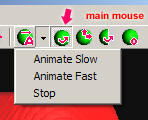
Main toolbar buttons for navigation mouse mode: Rotate, Pan, Animation,
Clipped rotation, etc.,m changing Light options.
Buttons,
from left to right:
1)
Animation On/Off, use pop-up submenu to select animation speed
2)
Mouse Rotate mode,
This is the main mode that permits you to pick up the objects in 3D scene,
and rotate scene while no object clicked
The default mode
3)
Mouse Pan Mode, Pan the scene with right mouse drag
4)
Mouse Rotate Clipped Mode
In this mode mouse will rotate the surfaces relative to coordinate system
and relative poi the tools too
It is useful in combination with clip planes and clip Cube (see tools below)
5)
Reset all angles to default
4. Tools
4.1 Overview
There
is a set of unique interactive tools for measurements in 3D screen, left
tool bar can be used to call some of them.
Tools
are moved by left mouse in 3D scene. To unable tool pick up use either
Main mouse mode or Rotate Clipped mouse mode.
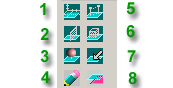
Buttons:
1)
Axis On/Off
2)
Clip Plane On/Off
3)
Stereo Marker On/Off
4)
Report tool
5)
Distance measuring tool On/Off
6)
Volume measuring cube tool, also used for volume clipping
7)
Mouse position XYZ read out
8)
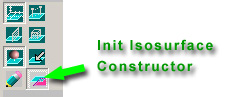
Isosurface constructor
4.2 Clip Plane
Click
left toolbar button 2. See the plane. Adjust the plane position by left
mouse.
NOTE:
Main mouse mode as shown below.
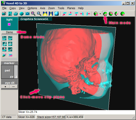
Fig.2.
Screen Shot 4D CT. Clip plane ON. Use mouse in 3D screen to adjust plane
position. Main mouse mode active.
Now you can hide the plane Menu>Planes>Y Plane for better visibility.
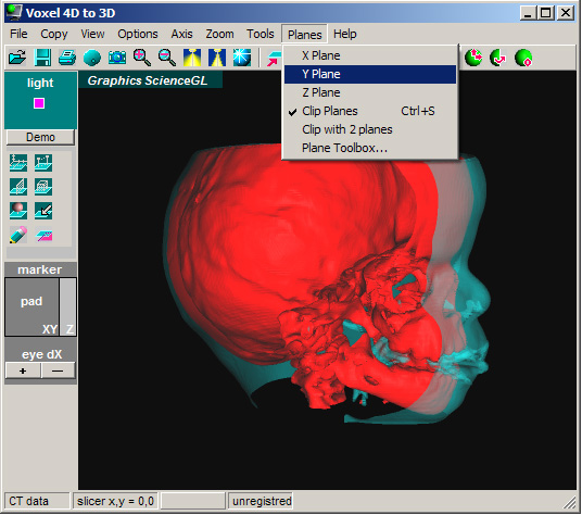
Fig.3. 4D
CT image stack to 3D iso-surface shot. Clip plane Off while Clip continue to
be active.
Select Rotate Clipped Mode from main toolbar as shown below. Activate Axis (optional). Rotate surfaces relative to clip plane with right mouse.
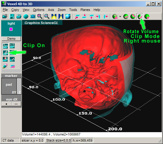
Fig.4.
Clip plane Off while Clip continue to be active.
You can examine surfaces using double plane (dicer) that is activated from Menu>Planes>Clip with 2 planes. From same submenu enable Y cut plane, enable clipping, enable double plane clipping.
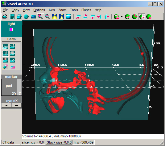
Fig.5. 4D
CT image stack to 3D iso-surface shot. Plane is active. Clip plane is ON. Clip
with 2 plane mode is On.
Try to move the slicer plane with left mouse.
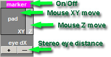
4.3 Stereo Marker
Click left toolbar button 3 to activate stereo marker. Alternatively you can click "marker label" to do so.
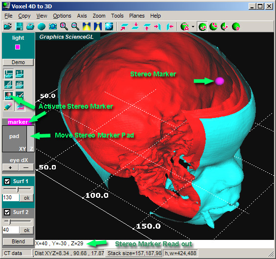
Fig.6. 4D
CT image stack to 3D iso-surface shot. Stereo Marker ON.
Moving marker in 3D space is demonstrated.
Use
marker pad to move marker in all directions (XY left pad, Z right pad)
as shown below.
4.3 Distance Measuring Tool
Click left toolbar button 3 to activate stereo marker. Alternatively you can click "marker label" to do so. Enable report with left toolbar button 4 as shown below.
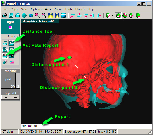
Fig.7.
Plane is OFF. Clip is ON. Distance Marker is ON. Report is active.
Disable clip plane to access inside surface features with mouse. Click anywhere on surface to drop the marker. Move mouse over other surface points to measure Distance and XYZ components of the distance. If you have both stereo marker and distance marker active you will read out marker to marker distance as well. See below in report window and status bar.
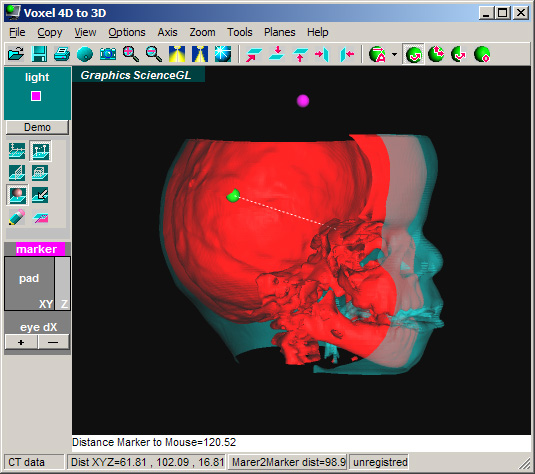
Fig.8.
Distance Marker ON. Stereo marker ON. Report active.
Use Rotate clipped, Axis and Zoom/Pan for exploring data more closely.
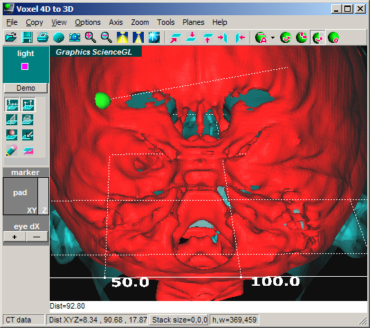
Fig.9.
Distance Marker ON, Axis ON, Clip plane active, Zoom used to see inside
surface. Rotation Clipped is active.
4.4 Volume Measuring Tool
Disable clip plane. Click Volume Cube button within left toolbar. By default the volume cube is clipping the surfaces. You can turn clip with volume On/Off from Menu>Tools>Volume Clip.
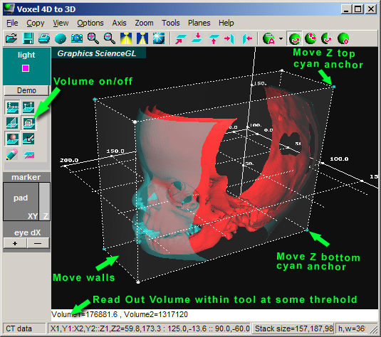
Fig.10.
Volume Cube Tool ON. Clip with volume is ON.
Try
to resize volume in all directions by moving walls and anchors with left
mouse.
NOTE:
White anchors and cyan anchors behave differently.
Try
to move volume as a whole with right mouse.
4. Isosurface Constructor
You
can skip this session if you work with default surfaces.
You will see isosurface tools separate for 1st and 2nd surface construction. d level for both surfaces.
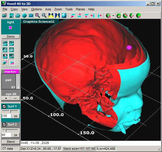
Fig.11.
Surface constructor ON. Blend option OFF, i.e. surface 2 is solid.
You can construct 2 surfaces with any
voxel level of interest that is called threshold. Following options are
available:
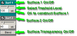
You can
select threshold either by slider or typing in corresponding text box.
Press
OK to construct isosurface layer.
Use
Blend option to set the transparency of the second cyan layer.
See
effect of threshold level selection below.
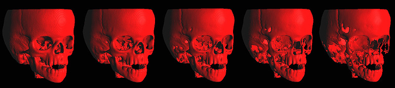
Fig.12.
Threshold level from 130 to 160 on byte (255 levels total) voxel stack,
level is increasing from left to right.
Visit www.sciencegl.com
for more hints and news
| 3D art ActiveX GIS map Forensic 4D volume Laser Multilayer CCD IR images Resources 1 2 3 4 Bio Imaging Hybrid AFM | |
| Europe FringeCatch AFM Products | |
|
Address: 140 North Main St., Suite 2A Attleboro, MA, 02703 / Phone: (401)-323-0603 (voice) |
|
ATI™ is used under license
and is a registered trademark of ATI Technologies Inc. in the United States
and other countries.
OpenGL
is a registered trademark of SGI
-----------------------------------------------
Copyright
© 2003-2013 ScienceGL,
Inc.