Content
1. Overview
2. Installation
3. 3D Surface Visualization
3.1 General
3.2 Drawing 3D Labels: Methods and description
3.3 Saving AVI movies, animated clips
4. Properties and Property Pages
5. Events
6. Mouse Operation, 3D Tools
6.1. General Mouse Operation
6.2. Volume Measure Tool
6.3. Mouse Position Read-out Tool
6.4. Area marking with boxes
6.5. Markers Pins and Distance Tool
6.6. Arbitrary Located Cut Plane
6.7. 3D Axis
7. 3D Volume 3D Voxel Visualization
7.1 Voxel to 3D surface
7.2 Drawing Triangle 3D Objects
7.3 Volume Segmentation
7.4 Volume and Area Measurements
8. Registration and support
9. Licensing
1. Overview
3D voxel 4D volume PRO is an interactive component (ActiveX control or/and .NET native component) that is designed for advanced visualization of the 3D and 4D data sets as iso-surfaces in 3D space. The surface to be visualized can be produces from structured mesh, vector surface or 3D/4D voxel (volume) stack. The control utilizes OpenGL library to produce 3D rendering of various data sets. This guide is intended to be used together with CPP, C++ , C#, VB, or .NET SDK sample code enclosed to the package. Note that we provided full 3D functionality through public access to the component, in a stable and reliable manner, preserving critical areas of the operation. For advanced users we can open more access into internal procedures, variables and processing. Please contact us for specific requirements. We also provide custom features for advanced users.
The software has been tested with Windows 95/98/NT/2000/XP. We recommend at
least 2 GHz processor and 512 MB RAM.
New: The software was recently tested with Microsoft Windows Vista OS.
2. Installation
Run MSI installation program from the installation CD or downloaded install package. Installation process is automatic. The setup program might ask you a permission to update some system files. Please allow it to do so. We use latest system files from Microsoft (MS). Please contact us if you encounter any problems with installation. We provide programming sample code for most of the control functionality. They can be found in SDK section of our installation CD.
3. Surface visualization
3.1 General
DataByPointer
The method is used to pass array of elevation data (regularly spaced, structured
mesh) into control. The data is passed as Z elevation points organized into
1 or 2 dimensional array of the Float type. The method is used in STILL surface
mode.
void DataByPointer(long* SarrayPTR, long NumPointsX, long NumPointsY);
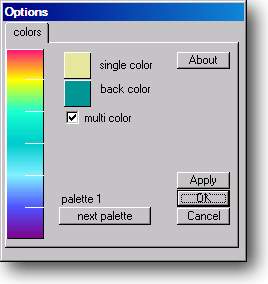
PaletteDlg_M
Brings dialog to change palettes and back color.
The operation within form:
1. Changing palette to other pre-programmed: Click :: next palette:: button.
The control provides up to 10 palettes.
2. Changing (customizing) colors within any palette: Click on any of 8 colors
on palette, color selection must appear. Select different custom color.
3. Apply: Click ::apply:: button to see changes
4. Monochrome palette (single color for the whole surface): Uncheck multi color
option box. Select desirable color for surface.
void PaletteDlg_M();
Zflip
Flip 3D surface in Z axis relative to middle Z point.
FilterZ
Cuts some points Above and Below given Fmax, Fmin, To be exact it sets those
point to Fmax or Fmin values
" Fmax, F min are the maximum and minimum cut-off elevation Z-values
" Autoscale option flag rescales Z axis of 3D to fit into the whole palette
range
RenderToClipboard
Pass 3D picture as BitMap to clipboard, ready for paste into picture post processing
software like Photo Editor.
Display
Update the 3D scene. This actually redraws current 3D scene.
GetSlicerPos
Read current position of the slicers on the surface in xy plane. Corresponds
to index of the array passes into control.
void GetSlicerPos(long* posX, long* posY);
Get3Dpicture
The method returns standard windows picture with 3D content. Used in a call
like this:
CPicture Get3DPicture();
GetFlat2Dpicture
The method returns standard windows picture with 2D projection content. The
projection is made to xy plane. You can use this function to pass standard OLE
picture to any control such as pictureBox.
The Colored parameter indicates if you want to get Z palette colored picture
(True) or gray scale one (False).
The size of the picture returned is equal to pixel xy size of the surface under
visualization.
CPicture Get3DPicture();
GetScalePicture()
Returns standard windows picture with color palette box (sub window) drawn at
upper right corner.
CPicture GetScalePicture();
Render3DToJPG
Makes jpg file with 3D picture of given size in pixels,
Parameters: newWidth, newHeight are the output size controlling parameters,
ForceBackColor is the color of desired background output, FileName is the full
path of file to be saved
void Render3DToJPG_C(BSTR* filename,
long NewWidth, long NewHeight, short JPGquality,
long ForceBackColor);
RenderAllToJPG
Same as the above, except that this also draws palette Scale picture into the
output file.
void RenderAllToJPG(BSTR* filename,
long* outWidth, long* outHeight,
short* JPGquality, long* ForceBackColor);
Print3D
This method Prints to 3D window. It takes same parameters as RenderJPG. The
method before printing prepares the image of the size given by NewWidth, NewHeight
in pixels. After that it sends the picture to the printer.
void Print3D(long* NewWidth, long*
NewHeight, long* ForceBackColor,
BOOL* printScale);
UpdateSurface
This method updates the surface in the sense that it constructs it anew. Normally
you don't have to use this method as updates are automatic. However if you encounter
a situation when the surface does not updated auto after some operation you
can use this method. AutoScale flag indicates that while surface is being constructed
it gets auto scaled into full Z scale of the palette.
void UpdateSurface(BOOL* AutoScale);
3.2 Drawing 3D Labels
The control allows to draw up to 256 lables in 3D space, each having own location, orientation, size, color. The labels are stored in internal collection.
AddMessage
The method is used to add/delete message from collection. To delete message
just pass String_MSG as empthy "" string.
Parameters: MsgNumber is the short between 0 and 256 (clipped if otherwise),
String_MSG is the string that will form the label to visualize in 3D. Pass empty
string i.e. "" for deleting message, X1, Y1, Z1 are the coordinates
of message in, MSGcolor is the color of the label in long representation, nGamma,
nBeta is the orientation angles in Degrees.
NOTE: Each message can have its own color, font orientation, size, position,
etc.
void AddMessage(short* MsgNumber, BSTR* String_MSG, float* X1, float* Y1, float* Z1, float* fSize, long* MSGcolor, float* nGamma, float* nBeta);
MessagesVisible
This is used to make all non-empty messages visible/invisible
BOOL GetMessagesVisible();
void SetMessagesVisible(BOOL bNewValue);
3.3 Saving AVI movies, animated clips
AVIsaveDLG
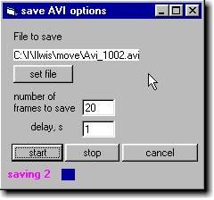
The method generates dialogue used to initiate and set some options of the animated clip file (AVI). The use of this feature might need the CODEC filters installed on your PC. CODEC is coding-decoding filter used to compact your data for optimum file size/quality ratio. There are several Codec's available and included into Windows 95/98/NT/Me/2000/XP. Some others are available on WEB as commercial products or for free. We do not include Codec's in our distribution package. Please contact us for details on Codec's use and installation. Contact ScienceGL if you experience problems with compacting AVI files. You can always use non-compacted option for saving AVI and compact the files with dedicated software. If you are not experienced in using codec's we recommend to use stable (but not the most effective) "Cinepak Codec by Radius" in compacter selection dialogue.
The dialogue is used to name output file, adjust some options and provide visual control of AVI creation process. On pressing Start you will get compacter selecting dialogue.
The <Set file> button is used to name output file. On loading form last
file saved is used as default name.
Use "Number of frames to save" box to set desired number of frames
(within 2...500).
Delay, s indicates the time interval between <Start> button click and
actual start of frames saving (within 0...100 in seconds). Delay active sign
is shown during delay time as hourglass picture left of the delay box.
Status of the current AVI progress is displayed at lower part of this form "saving
frame number" and progress bar.
4. Properties and Property Pages
Property SlicerOpacity Get, Set float range 0 to 1.
Makes slicers more or less transparent used for better visibility of planes.
Actual Visual effect depends on OpenGL driver implementation. This property
is also accessible from Property Page.
ScrollsVisible Get, Set Boolean
Makes scrolls visible / invisible. Scrolls are used for moving surface in x,y
plane to provide more detailed view for Zoomed surface. Use Method SetScrollDef
to return scrolls into default 0,0 position.
SurfVisible Get, Set Boolean, default value is FALSE
Makes surface within control visible/ invisible after you pass the data
ShowArrow Get, Set Boolean
Orientation arrow marker on/off
NOTE: Orientation marker is located on lower part of the surface and shows arrow
in X axis direction. The marker is designed to provide fast orientation in rotating
surface.
ShowColor Get, Set Boolean
Toggles surface elevation colored/ monochrome. Both random points and structured
mesh modes.
RotateDirection Get, Set short
Sets or gets direction of animated rotation of the surface
Permitable values 1 or -1 default value is 1
PalettePath Get, Set CString
Multiple palettes sets can be preserved by setting different users some different
path for custom palette file. Each palette file has 10 user defined palettes.
This property sets or gets the Full path of the location of the palette file.
Palette file must have "*.cfg" extension otherwise error message appears.
Path must be valid existing) otherwise error message appears. Use this property
if you have several users.
CBackColor OLE_COLOR
Standard property used in addition to palette changing form. OLE_COLOR is long.
Animation Get, Set Boolean
Toggles Animation (rotation of the surface) on/off.
AnimationTimer (Time Long) range is from 10 to 2000
Set desired timing of the frames in ms (milliseconds)
Note: On slow PCs actual animation rate will depend on speed rather than on this value.
LightIntensity Get, Set float Range From 0 to 5
Changes intensity of the light applied to the 3D scene.
Following 3 properties are designed to control orientation of the surface in
3D space. Angles of orientation as follows:
Alpha Get, Set long angle in degrees, range (-90...90)
Beta Get, Set long angle in degrees, range (-90...90)
Gamma Get, Set long angle in degrees, range (0...360)
Default values: Alpha = -30 , Beta = 0, Gamma = 0 are set after first control
initialization.
LightPositionX Get, Set, float
Controls X position of the light source relative to (0,0) origin. Recommended
usage: for better visualization of fine structure of the surface use inclined
lightning.
LightPositionY Get, Set, float
Controls Y position of the light source relative to (0,0) origin. Recommended
usage: for better visualization of fine structure of the surface use inclined
lightning.
Font Get, Set, OLE font
This sets or returns the font of the labels inside palette box (sub-window)
Zoom Get, Set, float range (0.1 ....6) default value 1
Zooms surface in all 3 directions x,y,z
zZoom Get, Set , float range (0.1 ....6) default value 1
Zooms surface in Z axis direction (height)
ZoomX Get, Set float range (0.1...10) default value 1
Zooms surface in X axis direction, used for changing surface aspect in x,y plane.
ZoomY Get, Set float range (0.1...10) default value 1
Zooms surface in Y axis direction, used for changing surface aspect in x,y plane.
Height Get, Set long
Width Get, Set long
Standard properties
DataCompress Get, Set Boolean default value is True
Internal data compression designed to speed up rendering process at expense
of some quality loss. The compression provides faster rendering at the expense
of quality. Works as "Low pass filter" removing fine structure from
the surface. Effect of this filter is practically invisible for smooth surfaces.
Recommended for the surfaces of 256x256 and bigger size.
FastRender Get, Set Boolean default valie is True
Internal data render accelerator designed to speed up rendering process at expense
of some quality loss. If FastRender is OFF, the surface is constructed as Multi-triangle
with smooth change of color (gradient fill) between 3 points, this provides
best possible output, but requires significant calculation. Effect of this filter
is practically invisible for smooth surfaces. If FastRender is ON, speed is
optimized at the expense of quality of the output.
sliceXvisible Get, Set, Boolean, default value is False
Toggles orthogonal Slicer ON/OFF
sliceYvisible Get, Set, Boolean, default value is False
Toggles orthogonal Slicer ON/OFF
sliceZvisible Get, Set, Boolean, default value is False
Toggles orthogonal Z Slicer ON/OFF
SlicerZoom Get, Set float range 0.1…10 default value is 1
Change vertical Z size of the semitransparent cut planes (X and Y slicers).
For some flat surfaces you might want to increase size of the slicer for easier
operation. At SlicerZoom=1 the vertical Z size of the slicer is determined automatically
from maximum and minimum Z values of the surface.
PaletteN Get, Set short
Set or Get the current palette number (range 1 to 10) if out of this range ignored.
The palettes are set and saved with palette constructing dialogue called by
PaletteDLG call.
PaletteVisible Get, Set Boolean, default value is True
NOTE: toggle paletteVisibe affects effective width of the 3D rendering window,
see Width property for details.
Diffuse Get, Set Boolean, default value is False
Makes surface 100 Short diffused reflecting (suppress shadows and specular reflection)
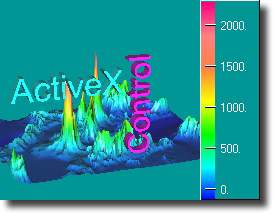
ContourLine Get, Set Boolean, default value is False
Use this property to visualize contour lined surface, see example picture below.
Contour lines help to analyze elevation structure of the surface.
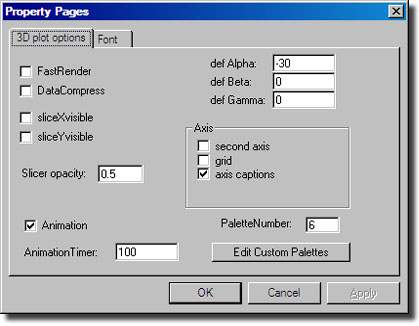
Property Pages
The property page allows you to set some options during design time. Default angles are used if you want to reset into some defined position after user used rotation/animation of the surface. The page also provides access to color palettes that you can use in both develop and run mode. NOTE: in both cases from property page or from run time application the palette colors are saved (preserved) in the same manner. Means that color/palette selection is identical for both run and develop modes. Animation timer units are milliseconds.
5. Events
The control implements built-in orthogonal slicers that are visualized as semitransparent
planes. The slicers are user clickable and movable by Drag mouse operation.
They are used to provide user intractable way of choosing some surface cut position.
The orthogonal cutting planes (Slicers) are named as follows:
SliceX is the slicer parallel to X axis (X cut plane)
SliceY is the slicer parallel to Y axis (Y cut plane)
In addition to Events you can always get slicer position by GetSlicerPos method
Event ScaleMouseUp
Raised when mouse is up over Palette scale
OnScaleMouseUp (short FAR* Button, short FAR* Shift, float FAR* x, float FAR* y)
Event SliceXmouseMove
Raised when user moves slicer.
Xpos returns current position of the slicer
OnSliceXmouseMove(long FAR *Ypos)
Event SliceYmouseMove
Raised when user moves slicer
Xpos returns current position of the slicer
OnSliceYmouseMove(long FAR *Xpos)
Event SliceXmouseDown
Raised when user clicks slicer
Ypos returns current position of the slicer
OnSliceXmouseDown(long FAR *Ypos)
Event SliceYmouseDown
Raised when user clicks slicer
Xpos returns current position of the slicer
OnSliceYmouseDown(long FAR *Xpos)
Similarly
Event SliceXmouseUp
Event SliceYmouseUp
Event SliceXmouseMove
Event SliceYmouseMove
Event ZplaneMove
Event Click
Event MouseDown
Event MouseMove
Event MouseUp
Raised anywhere, but over Palette scale Sub window
For Events associated with 3D tools see next section.
6. Mouse Operation, 3D Tools
6.1. General Mouse Operation
Mouse operations are very intuitive. Just try to drag mouse without and with
Shift/Alt keys. Detailed description is as follows:
Plane Left pressed mouse dragging within 3D window normally results in ROTATE
operation (angle changing) within 2 planes. Vertical movement is Alpha angle
(ZY plane), horizontal movement is Beta angle (ZX plane).
If Ctrl key pressed while dragging you get Gamma angle rotation (in XY plane).
If Shift key pressed while dragging you get PAN operation indicated with "Hand"
cursor.
If Alt key pressed while dragging you get ZOOM operation indicated with "Magnifier"
cursor.
NOTE: For All Rotate, Pan and Zoom operations you should not hit any of tools
in the moment of mouse is Down.
Otherwise control interprets operation as if you want to interact with tool.
6.2. Volume Measure Tool
The tool is turned on/off by property
ShowVolumeTool Get, Set Boolean, default False.
The tool is interactive and can be used with mouse inside of the 3D window.
The tool is formed as the box in 3D space. The box is defined by XYZ positions
of the anchors. The anchors are movable in real time to provide better view
of the area (volume) selected.
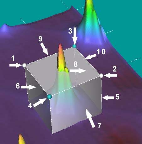
Volume tool
Clickable features: Left Mouse
1. White anchor, sphere: Operation Drag (mouse down and move) used to change
XY position of anchor, which results in XY resizing of the box.
2. White anchor, sphere: Operation Drag (mouse down and move) used to change
XY position of anchor, which results in XY resizing of the box.
3. Cyan anchor, sphere: Operation Drag (mouse down and move) used to change
Z position of the upper plane. Results in resizing of the box height.
4. Cyan anchor, sphere: Operation Drag (mouse down and move) used to change
Z position of the upper plane. Results in resizing of the box height.
5. Side corners of the box, Vertical white lines: Operation Drag (mouse down
and move) used to change XY position of anchor, which results in XY resizing
of the box.
6. Side plane of the box: Operation Drag (mouse down and move) used to change
XY position of anchor, which results in XY resizing of the box.
7. Side plane of the box: Operation Drag (mouse down and move) used to change
XY position of anchor, which results in XY resizing of the box.
8. Side plane of the box: Operation Drag (mouse down and move) used to change
XY position of anchor, which results in XY resizing of the box. Note even though
upper plane is semitransparent. The drag mouse "through" upper plane
will activate side plane rather than upper plane.
9. Edges at the Upper Plane, white lines: Operation Drag (mouse down and move)
used to change Z position of the upper plane. Results in resizing of the box
height.
10. Edges at the Upper Plane, white lines: Operation Drag (mouse down and move)
used to change Z position of the upper plane. Results in resizing of the box
height.
Clickable features: Right Mouse
Any clickable 3D object above if used with Right mouse produces Volume Tool
Move effect: Operation Right Mouse Drag. This moves the tool as the whole in
XY directions without changing the size.
Volume Tool Properties
ShowVolumeTool Get, Set BOOL default False
Toggle volume tool on/off.
VolumeReportVisible Get, Set BOOL default False
Toggle Report sub-window on/off. Report is a built-in sub-window that shows
the volume tool information
VolumeOpacity Get, Set float range 0…1
Volume Tool Methods
GetVolumeCoord Get current position of the Anchors
SetVolumeCoord Set current position of the anchors, also update tool to the
position passed.
void GetVolumeCoord(float* X1, float*
Y1, float* X2, float* Y2, float* Z1, float* Z2);
void SetVolumeCoord(float X1, float Y1, float X2, float Y2, float Z1, float
Z2);
Volume tool Read Out Event
VolToolMove
The event fired when you move (resize) volume tool with mouse. The event returns
corners (anchors) positions of the volume measuring tool.
OnVolToolMove(float FAR* X1, float
FAR* Y1, float FAR* X2, float FAR* Y2,
float FAR* Z1, float FAR* Z3)
6.3. Mouse Position Read-out Tool
The tool is designed to how X,Y position of the mouse while user moves mouse over the surface.
MeasureXYZmode() Get, Set Boolean
Enables or disables Mouse Position Read-out Tool. Make it true to receive the
MouseXYZ event
Actual read-out is performed by corresponding Event.
MouseXYZ
This event reads X, Y, Z position over the surface point in i, j units of the
array passed. The event is not fired when mouse is out of the surface.
OnMouseXYZ(float FAR* X, float FAR* Y, float FAR* Z)
MeasureXYZmode Get, Set Boolean
Enable and disable mouse measurement.
6.4. Area marking with boxes
Set3DOpenBox
Make a box visible at some position on the surface.
Parameters:
bID Box ID use number within 1…128 range, means you can drop up to 128
boxes.
bx1, by1, bx2, by2 position of the 2 anchors on the surface in unit of Array
indexes.
bColor win long color of the box
void Set3DOpenBox(long bID, double
bx1, double by1, double bx2, double by2,
long bColor);
ShowBoxes Get, Set Boolean
Toggle boxes visible/invisible.
After the box is set it is interactively moved with mouse drag operation. The
Area coordinates are returned by method
Get3DOpenBox
Current anchors positions of the box of given ID
void Get3DOpenBox(long bID, double
*bx1, double *by1, double Fbx2,
double *by2);
6.5. Markers Pins and Distance Tool
Markers are pin-like objects that can be dropped on surface at position of the interest.
SetMarker
mID number if the pin (1…128)
mStyle, pin style default sphere (contact us for current styles description)
mi , mj, indexes of the pixel where pin has to be drawn
mColor win color of the pin
mSize size of the pin head in surface pixel size unit
void SetMarker(long mID, long mStyle, long mi, long mj, long mColor, float mSize);
ShowPins Get, Set Boolean
Toggle all pins on/off
GetMarker
Return marker position in terms of i, j indexes of array (location) and Z value
at this location.
BOOL GetMarker(long mID, long* mStyle,
long* mi, long* mj, double* mZ,
long* mColor, float* mSize);
You can use 2 markers connected to each other in Distance Measuring Tool.
The distance tool ALWAYS connects marker with ID=1 and ID=2.
To use the tool, you should drop markes 1 and 2 at some locations and then unable
Distance Tool
ShowDistTool Get, Set Boolean
Unable/disable distance tool.
Use DistanceToolMove event to read back xy positions of both pins that form the distance tool.
Event DistanceToolMove
Reads out distance as marked with tool. Also used for Arbitrary Cut, see below
OnDistanceToolMove float FAR* X1, float
FAR* Y1, float FAR* X2, float FAR* Y2);
6.6. Arbitrary Located Cut Plane
This tool is used to set Free hand intersection of the surface and vertical
plane.
The Cut plane is connected to distance tool. The difference is that the semi-transparent
plane is also shown.
The plane helps to see intersection right in 3D window
ShowArbCutTool Get, Set Boolean
Enable/disable tool
Similarly with Distance tool the Arbitrary Cut Plane is ALWAYS connects marker
with ID=1 and ID=2.
To use the tool, you should drop markes 1 and 2 at some locations and then unable
the Tool.
Property ShowDistTool Boolean get set
Unable/disable distance tool.
GetArbCutPlane
You can read out plane position by this call. XY unit space is same as i, j
indexes of array.
BOOL GetArbCutPlane(float* X1, float* X2, float* Y1, float* Y2);
Event DistanceToolMove
Read out Arbitrary Cut position and Distance, see above
6.7. 3D Axis
XY Axis is auto formatted in relative units (0 to 1) by ShowAxis call. You might need different formatting for the XY for your data.
FormatXYaxis
This is used to format axis that is drawn in 3D scene.
You should provide following parameters:
umPerPixelX step in X direction (microns or any other unit per pixel)
umPerPixelY step in Y direction (microns or any other unit per pixel)
stepX , stepY step in between the ticks shown on x y axis also in microns (measurement
unit)
FontSize size of 3D font drawn on axis. This size is related to pixel units,
not microns.
We recommend this to be about 1/20 of the actual surface pixel size.
aColor color of axis in Windows long representation.
Z axis depends on the data under visualization. It is formatted automatically.
You can change number of Z ticks is changed by clicking Z palette picture in
right-upper corner
Left mouse click = less ticks
Right mouse click = more ticks
void FormatXYaxis(float umPerPixelX, float stepX, float umPerPixelY, float stepY)
You can control Axis appearance by following properties:
ShowAxis Get, Set Boolean (default False) makes axis visible.
SecondAxisVisible Get, Set Boolean (default False) makes secondary axis visible.
GridVisible Get, Set Boolean (default False) makes axis grid visible.
AxisCaptX Get, Set CString access to axis caption to be shown.
AxisCaptY Get, Set CString access to axis caption to be shown.
AxisCaptZ Get, Set CString access to axis caption to be shown.
CaptVisible Get, Set Boolean Caption visible on/off.
AxisFontSize Get, Set float the size of the labels shown on axis.
AxisZPosition Get, Set float vertical position of the XY axis and grid
AxisColor Get, Set long windows color representation, default White.
AxisXoffset Get, Set float starting X value for axis
AxisYoffset Get, Set float starting Y value for axis
FormatXYaxisDefault
This will format axis to default appearance using current surface data. The
method shall be used after DataToShow.
Axis dialog called by PaletteDLG call and selecting axis TAB.
7. Volume Voxel Visualization
7.1 Voxel to 3D surface
General
We use 2 separate modules built into control to provide you with voxel to surface
visualization.
1. 4D Voxel stack to 3D iso-surface constructor, which outputs 3D objects.
2. Multiple layer 3D engine for object visualization.
With module 1 in general operation is easy just sending array of data and 3D
surface automatically calculated. Surface can be sent to 3D scene or saved for
future use. The surface is automatically located to x=0, y=0, z=0 center of
the 3d world for easier visualization. Surface is constructed as isosurface
that covers the volume of certain threshold. You can construct several isosurfaces
and observe them together. The array (signal data at each voxel) can be byte,
short or long. You will only need to know the valid range of the signal to be
able to select suitable threshold.
You can construct 3D objects from stack every time you run your application,
but this is not optimum approach as voxel processing is relatively slow. We
suggest you to process voxels only ones and keep ready isosurfaces in corresponding
files.
After files are constructed you can read them fast for 3D visualization..
3D visualization engine in fact is almost the same for both surface and volume. Except that you will not be able to use some of the features like compression and some of the surface specific3D tools.
Calls
MakeVoxelBuff
This must be the first call which prepares the voxel array
void MakeVoxelBuff(long sW, long sH, long sz);
ArrayVoxelsBptr
This will pass Byte array of voxels to component
UpperX, UpperY, UpperZ are the upper bound of the array.
void ArrayVoxelsBptr(long upperX, long upperY, long upperZ, long ptrArrayB);
ArrayVoxelsSptr
Same as ArrayVoxelsBptr but short array
void ArrayVoxelsIptr(long upperX, long upperY, long upperZ, long ptrArrayB);
ArrayVoxelsLptr
Same as ArrayVoxelsBptr but long array
void ArrayVoxelsLptr(long upperX, long upperY, long upperZ, long ptrArrayB);
SegmentVolume
This will bring additional form to perform segment with growing region type
segmentation.
(this is only implemented upon additional request)
SetMetrixOfVoxels
Step per voxel in all 3 directions
Should be called before making Triangles
void SetMetrixOfVoxels(float stepX, float stepY, float stepZ);
SmoothVolume
Perform Voxel smooth of desired blur. Blur range is 1 to 5, recommended Blur=1.
void SmoothVolume(long Blur);
MakeTriFromVolume
Construct the iso surface at certain level of threshold and make triangle model.
void MakeTriFromVolume(float TresholdLevel);
KillVoxelBuffer
Stack buffer might be big. You can free memory after you construct all layers.
NOTE: you will need this buffer to calculate volume.
VoxelArrayOK
Check if voxel stack buffer is available within the control. This call returns
buffer status.
BOOL VoxelArrayOK();
CalcVolume
This call will return Volume within Volume tool (Cube) and within threshold
value CutOffLevel. This is equivalent of calculating volume inside some object
of CutOffLevel threshold.
float CalcVolume(float CutOffLevel);
SetCurrntSurfAsObj
After you create some iso-surface with MakeTriFromVolume call you can pass triangles
to object of given ID. This call will create 3D visualization object from the
surface that was calculated from voxel data. You can pass several iso-surfaces
to several corresponding objects of unique ID. You have to follow sequence of
ID's starting from 0, i.e. first object to be created MUST HAVE ID=0.
void SetCurrntSurfAsObj(long id);
SaveTriangles
Save 3D model to file for later use. The file will contain Triangles, voxel
size of original data and processing options.
This is performance optimization feature. You will find that it is much faster
to load ready triangles into 3D engine as compared to calculation of the object
from the voxel stack. This is especially helps for big stacks and medium power
PC's. After you saved triangle object to the file you can load the file with
following call.
void LoadTriForObj(LPCTSTR FullPath);
LoadTriForObj
Load 3D model from the file for visualization as object number ID. The file
contain Triangles, voxel size of original data and processing options. *NumTri
returns number of triangles found in the file. FileName is full path of the
file to be loaded.
NOTE: Files to load must be the same as saved by SaveTriangles call
void LoadTriForObj(long ObjID, long* NumTri, LPCTSTR FullPath);
Clip Planes, Volume Slicing
You can use 3 orthogonal planes to clip and slice the volume. You need to enable each plane
ClipZplane , ClipXplane, ClipYplane Boolean Get, Set
Set or return status of Clipping for each of 3 orthogonal planes. If set True,
then one side of the 3D scene will be clipped.
ClipWith2planes Boolean Get, Set
Slicing is done with double plane. Each X, Y and Z plane can clip volume in
such way that only slice is visible. If set True, clipping of volume is performed
as Slice.
VolumeToolClip Boolean Get, Set
Set or return status of volume tool. If set true volume outside of Volume Tool
cube will be invisible
VolumeOpacity float Get, Set
Set or return Opacity of the volume tool. Range from 0 to 1. Zero corresponds
to transparent Volume Tool.
AxisSize long Get, Set
You can control the size of the axis in Voxel unit. We recommend to keep axis
close to voxel XY size of the volume stack.
7.2 Drawing Triangle 3D Objects
General
You can send triangle objects to the control. The control accepts array of
triangles composed of vertexes. You can also load objects into control from
our files of *.v3o extension. The file contains triangles and some support information
about voxel size of the original data as well as processing options. Triangle
object file is created by SaveTriangles call. Loading data from files is the
simplest way to supply objects to control. We recommend that you to use only
this method. You can pass (load) several objects of different color, transparency
and visibility (on/off) into control. For performance consideration each object
is compiled into 3D scene and kept compiled until you need to change the appearance.
Each object is identified by unique ID number starting from 0 to ObjNumber-1,.
where ObjNumber. is the total number of the objects to be visualized. This ID
should be used for all the rest of the visualization (for sending data, changing
appearance etc.).
If your object was created internally from 4D stack, then you can pass it to
visualization module as well. After this it behaves same way as loaded objects.
PLEASE NOTE: OBJECTS MUST BE GENERATED FROM THE SAME STACK or at least from
the stacks of the same XYZ dimensions if you want to compare different stacks.
The control permits flexible scene visualization at different angles and camera positions. The rotation of the scene is achieved relative to origin (x,y,z all equal 0). For better flexibility you can translate the origin in x, y directions, so that you will rotate the scene relative to some point of interest on the scene.
We provide 2 lights for better visualization. One of fixed position and one movable by LightPositionX LightPositionY properties described in Section 5 of this document.
Calls
InitTriObj
Initialize several objects , where the NumObj is number of objects
This will prepare the control for receiving the objects. You should pass the
total number of the objects you will pass to control as ObjNumber parameter.
Note: you should not attempt to send objects before this call. Neither send
objects of ID number bigger then ObjNumber-1.
void InitTriObj(long* NumObj);
SetTriForObj
Send triangles to 3D engine as object iD. Alternatively you can use
void InitTriObj(long* NumObj, long PTRarray);
LoadTriForObj
Load 3D model from the file for visualization as object number ID. The file
contain Triangles, voxel size of original data and processing options. *NumTri
returns number of triangles found in the file. FileName is full path of the
file to be loaded. The File to load with this call must be the same as saved
by SaveTriangles call (see previous section for description). The first object
to be loaded with this call MUST HAVE ID=0.
void LoadTriForObj(long ObjID, long* NumTri, LPCTSTR FullPath);
ReturnObjectSize
Coordinates of object in 3D space, max and minimum values.
void ReturnObjectSize(long id, float*
X1, float* X2, float* Y1,
float* Y2, float* Z1, float* Z2);
ReturnObjVolInfo
After you load the triangle object file you might need to know what is the size
of the object in XYZ space and what were the processing options of creation
from voxels.
ID is the unique number for each object.
X1, X2 are the minimum and maximum values of X coordinate of triangles
Y1, Y2 and Z1 ,Z2 min and max values in other directions.
CutLevel is the threshold used to calculate iso-surface
SmoothN is the smooth blur level used while voxel stack was processed (typically
=1).
void ReturnObjVolInfo(long id, float* CutLevel, long* SmoothN);
FormatTriObj
Format object of given iD to provide necessary color and opacity.
Using this call you can set desired object appearance. You should do it for
the first time prior to following CompileObject call.
void FormatTriObj(long ObjID, long
WinColor, BOOL oVisible, float Opacity,
long drStyle);
KillTriObj (long ID)
Delete object oif given ID, free memory.
TriObjVisible(long ID) Get, Set Boolean
Visible on/off for any object of specified ID.
TriObjBlendON(long ID) Get, Set Boolean
You can set Semitransparent (blend) on/off for any object of specified ID.
CompileObject(long ID)
After you passed several isosurfaces to the objects you will have to compile
the objects using this call. The compiled object can be visualized with different
options. You can compile several objects one by one into 3D scene. While compaling
multiple objects please start with object ID=0.
IMPORTANT NOTE: The first object to be compiled with this call MUST HAVE ID=0.
ExtraLightON Get, Set Boolean
In some cases you might need to add extra light to illuminate some hidden (shadowed)
portions of the geometry. The extra light has fixed x=1000, y=100, z=100 position.
VolumeToolClip Get, Set Boolean
This Flag indicates if the volume tool clips the portion of the 3d scene outside
the tool.
CameraX, CameraY, CameraZ Get, Set float
Youj can set or read camera position in terms of input scale units (same as
vertexes). The default camera position is X=0, Y=0, Z automatically set depending
on xy size of the scene submitted into control. We suggest not changing Z position
of the camera. If needed zoom effects are achieved by Zoom property described
in section 5 of this document. Changing camera position is similar but not exactly
same as moving scrolls within the control. Moving scrolls will change point
to which observer is looking. In 3D terminology is often referred as cockpit
view point, i.e. some point at the scene being looked at. For simple applications
we recommend not to change camera position and just use scrolls to see different
points at the center of 3D window. This makes easier the application and provides
quite realistic visualization effects.
NOTE: You can make scrolls visible by setting ScrollsVisible property TRUE.
GetObjectsMode GET ONLY Boolean
This flag set TRUE automatically after you compile the objects into the scene
with CompileObject call.
VolInsideTool
Volume is counted as all voxels inside of surface (object) of given ID and inside
of the volume tool CUBE. If the tool covers all the object, this value is equal
the WHOLE VOLUME.
Minimum Voxel to 3D visualization call sequence
MakeVoxelBuff prepare buffer
ArrayVoxelsB send voxel array
MakeTriFromVolume make surface 1
SetTriForObj prepare buffer for 1 3d object
SetCurrntSurfAsObj send triangles to 3d object
FormatTriObj set color and other options
TriObjVisible make 3d object visible
7.3. Volume Segmentation
General
You can perform basic segmentation task with internal Segmentation Module. The module, when initiated, brings a dialog form with all images of the volume stack.
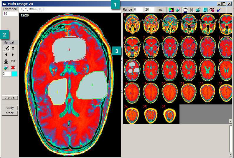
All stack images are located at the lower part of the form (multi-image picture, stack image browser). See stack frame images marked as 0…26 in the picture below. Let us call this multi-image picture as Stack Image Browser. Each image in the Stack Image Browser is constructed in accordance to the Pixel intensity, that we will call Pixel Signal. You can click on image within the Browser to bring corresponding stack image frame to the segment processor. The image clicked we will call Current Segmentation Frame. Corresponding 2D plot in sample picture below is marked as 2 seed with green markers. Within Current Segmentation Frame you can perform some segmentation selection.
7.3.1 Operation
You can initiate the module and the form using SegmentVolume() call. This will bring the form into the screen.
The frame passed to the Segment Processor (same as Current Segmentation Frame)
will accept interactive mouse click events. With mouse events you can choose
your segmentation options. If you do Left-mouse Click on Current Segmentation
Frame, you will drop the seed into the Current Segmentation Frame. The seed
is used to provide starting point for region growing segmentation. See picture
above, seed dropped is marked as a red cross. By dropping the seed point the
software will produce following actions:
We will call the Main Mask the array of the mask for voxels. This array has
the size of the voxel stack. We will call the Temporary Mask the array of the
current frame mask used for adding manual areas. This array has the size of
the single frame in the voxel stack. The Masks are drawn either as cyan for
Black-White mode or as Light-Gray for Color mode. The switching between the
BW-color modes is achieved by the "Color/Gray" button in the Main
tool bar (button 1 in Fig.2).
|
1
|
2
|
3
|
4
|
5
|
6
|
7
|
8
|
9
|
10
|
11
|
12
|
Main Tool Bar of Voxel segmentation form.
Description of GUI: Main Toolbar
1. Text box starting frame for Region Growing Selector
2. Text box end frame for Region Growing Selector
3. Button accept frame range. If not pressed setting ignored
4. Button toggle color/black-white mode of the form
5. Button redraw all masks and big picture.
6. Button toggle Region Growing Selection and Manual Area Selection
7. Button clean all mask in the whole stack
8. Button Load last mask saved
9. Button save mask
10. Hide form without unloading
11. Accept all masks and close form
The selection of the objects can be performed in two modes:
1. Region Growing Selection (RGS)
2. Manual Area Selection (MAS)
The mode is changed by button 6 in Fig.2.
7.3.3 Region Growing Voxel Selection (RGS) Mode
RGS is Default interaction mode. This mode is controlled with Region Growing toolbar

Toolbar for Region growing voxel selection. In the text buttons are numbered from 1 to 4, top-left to right-down.
Operation in RGS mode:
1. Start from any frame by clicking in the multiple image pictures.
2. Drop the seed by Mouse-Click operation in the Big Picture.
3. "Try mask" sample image is immediately created in accordance to
the seed. The "Try mask" carries the following information:
-White is the all pixels within tolerance range
-Cyan or Gray is the region grown from the seed
4. You can reconstruct the RGS by clicking different seed position and using
different tolerance.
5. When selection is satisfactory, you can click "OK" (Fig.2) to accept
the mask for this particular frame. The mask is passed to Main mask.
6. You can apply to Grow Region for all frames starting from the same seed.
Press "All Frames" button ( 4 in Fig.2) to apply to all frames.
7. You can repeat RGS for some range of frames by choosing range of interest
and accepting selection with "OK" button in Main Toolbar (0 in Fig.1)
Description of buttons Region Growing Toolbar
1. Drop Seed ON/OFF, when OFF no operation happens with clicks.
2. "x" Clear current selection
3. "OK" Accept selection for current frame. Pass Mask to Main Mask
Array.
4. Apply to all frames. Make Growing Region for the range of the frames. Pass
Masks to Main mask array.
NOTE: Shift Click operation is disabled.
7.3.4 Manual Area Voxel Selection (MAS) Mode
This mode is intended to correct some of the RGS produced frames. This mode is controlled with Manual selector toolbar. Depending on Color and Black-White representation the areas are drawn as colored or as white.
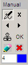
Manual Selector Tool Bar. The buttons are numbered from 1 to 8 as from top-left to right-down. Below is the number of the current selecting area. And color of the area.
The mask is accumulated in Temporary mask. The mask is combined with main mask after manual area is ready. The content of manual mask as constructed with RGS mode.
Operation in MAS mode:
1. Select any frame by clicking within multiple frames picture.
2. Draw any area with mouse. On Mouse Up event the area is redrawn and fill
seed for frame is auto-calculated to be somewhere in the middle of the area
drawn.
3. The number of area drawn is shown in lower portion of the toolbar.
4. If you draw some complex area, the auto-seed might fail and be placed outside
the desired area. In such case you can correct the seed position. Press "Return
to previous" area by the button 3 in Fig.4. Click mouse within selected
area to correct the fill seed.
5. You can use "Go to next area" area by the button 4 in Fig.4. Click
mouse within selected area to correct the fill seed.
6. You can try the manual mask by pressing "Try" button 5 in Fig.4
7. You can toggle all manual areas with buttons 4 and 5 in Fig.4. Any current
area can be deleted with button 2 or corrected on seed as described in #4 above.
8. When mask is ready button "OK" should be pressed. The manual Temporary
mask array is combined with Main mask array and picture is redrawn into Multiple
Picture on right side.
Description of buttons Region Growing Toolbar
1. Draw Areas ON/OFF, when OFF no operation happens with clicks.
2. "x" Clean current area. The number of the area is shown on lower
portion of the toolbar.
3. Previous manual area
4. Next manual area
5. Try all areas
6. "OK" accept all areas
7. Redraw all areas
8. "X" Clean all areas
9. Number of the current area and its color
7.4. Volume and Area Measurements.
You can measure volumes and areas with built into volume tool functionality
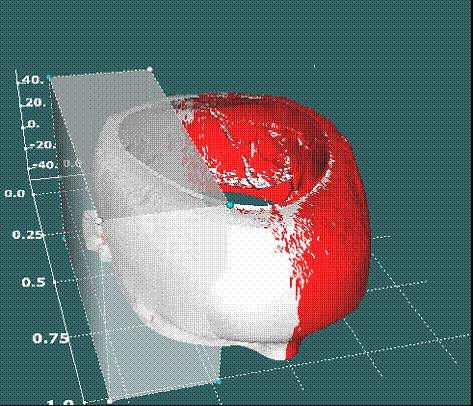
The volume is measured as all the voxels within specified object (same as within
certain threshold) and within the volume tool. The call is VolInsideTool, where
ID is the number of the object to be measured. The ID is the same as set by
object specifying calls (CompileObject for example, please previous section
for objects description). The call returns the volume.
The area is returned by AreaInsideTool(ID long, *LeftLookA double, *totalA double) where ID is the number of the object, LeftLookA ids the left looking triangles area (white in the picture above) totalA area total of all primitive triangles within the object. Again area is only counted within the volume tool. For the whole area you can set volume tool such as to cover the whole object. The tool helps you to select desired part of the object to be measured.
NOTE: we have colored "Left Looking" the triangles artificially just to explain functionality. In the control the object will not be colored.
8. Registration and Support
The control is protected against unauthorized distribution. The protection
is based on return code. For interested customers we can also provide alternative
hard key protection. Please contact for this feature.
Registered users are provided with online support.
IMPORTANT: The registration is based on Software code, which is unique for
each PC.
PLEASE BE SURE THAT THE CODE YOU SEND FOR REGISTRATION IS GENERATED
ON THE PC THAT WILL BE USED WITH 3D SOFTWARE IN THE FUTURE.
STEPS:
1. Call RegisterControl method. You can use optional message to be displayed
to the end user.
2. Copy the Software code (double click on number, get number blue-marked, use
Ctrl-C key stroke or right mouse click over the marked number to copy THE SOFTWARE
CODE. The copying is basically the same as if you use text processing program
like MS Word)
3. Send the Software code to info@sciencegl.com
4. Obtain the Registration key from ScienceGL
5. Run the program with RegisterControl method again.
6. Paste the Registration key into registration form
7. Press "REGISTER" button
Registered users of the PRO control are entitled to full support via e-mail
info@sciencegl.com
9. Licensing
You cannot distribute or transfer Developing time license. For details on distribution
of the RUN time licenses, please contact ScienceGL.
| 3D art ActiveX GIS map Forensic 4D volume Laser Multilayer CCD IR images Resources 1 2 3 4 Bio Imaging Hybrid AFM | |
| Europe FringeCatch AFM Products | |
|
Address: 140 North Main St., Suite 2A Attleboro, MA, 02703 / Phone: (401)-323-0603 (voice) |
|
ATI™ is used under license
and is a registered trademark of ATI/AMD in the United States and other countries.
-----------------------------------------------
Copyright © 2003-2012 ScienceGL,
Inc.